Understanding structural load paths

Load paths may not be straightforward in complex multi-level structures
All loads imposed on a structure must have a route down to the ground. This is the load path. Engineers designing new structures or modifications to existing structures need to be absolutely clear what the path is for every load, and that all of the elements on that path are strong enough to carry the load.
“The load path is like a chain,” says Jim Tod, temporary works director at consultancy Tony Gee and Partners. “It is only as strong as the weakest link. You have to follow the load path and make sure that every link on the path is strong enough to carry that load.”
Most load paths are quite straightforward. In a multi-storey building, the load goes through the slab or floor to primary beams, then out to the columns and down to the foundations. With a bridge, the load goes out from the deck to the piers and down to the piles or foundations.
Simple load paths
Vertical loads through a multi-storey building, self-weight ignored
Red arrows: load path; Green arrows: applied load

Vertical loads through a simply supported bridge, self-weight ignored
Red arrows: load path; Green arrows: applied load

In more complex structures, the load path may not be as straightforward. For example, if columns are left out to create an atrium in a building, the loads that would have gone through those columns will transfer sideways, and additional load will go through the remaining columns.
The load path must also include lateral loads from external factors such as wind and earthquakes. Wind load is something that will always have to be considered, whatever the location of the project or the type of structure.
Earthquake loading is essential for every building in known earthquake zones, including parts of Asia and the Americas, and can often be one of the key considerations in the design, as it was for the BBVA Tower in Mexico.

BBVA Tower, Mexico (credit: Ma. Dolores Robles-Martinez Gómez, Lourdes Legoretta)
It must also be considered for certain types of structure – for example, nuclear power stations – wherever they are located. The lateral load path through a structure may be different from that for vertical loads and is likely to include bracing, shear walls and/or the use of a lift core for lateral stability.
Every load path includes the connections as well as the structural members, and this can often be the weak link in the chain. “That’s where things can get missed out,” Tod says. “You might get the bolts or welds strong enough but not the plate.”
One purpose of determining the load path of a structure is to understand how the structure works as a whole, rather than merely ensuring that individual elements are strong enough to carry the load expected to go through them. Engineers should look at different possible load cases and make sure there is a suitable path for the loads to reach the ground.
Example: Ezhou City bridge collapse

In December 2021, four people were killed and eight injured when part of a bridge ramp collapsed in Ezhou City in central China. The bridge was undergoing repairs at the time and one lane was closed, so all traffic was flowing on the other side. An abnormal load had to be driven on the hard shoulder to pass the roadworks section, and the effect of this heavy load on the extreme edge of the deck appears to have resulted in the entire deck overturning.
“As no official reports have been issued yet, we can only speculate as to the cause of this failure, however the images available suggest that a global failure mechanism occurred, potentially caused by a combination of a relatively light weight superstructure, an absence of normal traffic, and the presence of a heavy load on the outside edge of the curved bridge deck. If this was the case, there may be no individual component failure - effectively the overturning forces from the live load could have overcome the restoring forces from the self-weight,” explains Chris Mundell, professional head of civil engineering structures and geotechnics at consultancy Atkins.
He adds: “It shows that you always need to step back and think in more global terms about what is going to happen when a load is applied, not just focus on the detail of each component.”
Example: Edinburgh school wall collapse
In 2014, a privacy wall in a school sports hall changing room collapsed, fatally injuring one 11-year-old pupil. The collapse occurred after one or more pupils standing in a gap between the privacy wall and the back wall of the building decided to support themselves off the floor by bracing their backs against one wall and both feet against the other wall. The privacy wall then toppled outwards.
More details of the event and the subsequent inquiry were published in 2018 in the report 'Fatal wall collapse at school due to wall climbing’ by CROSS-UK (Collaborative Reporting for Safer Structures).
The loads imposed by this simple action were higher than the values assumed in the relevant Eurocode. The collapse highlights the need to understand how a structure might be used to either ensure a certain load condition cannot be created or that a path for that load to follow is incorporated.
Alternative load paths

Vasco da Gama cable-stayed bridge, Lisbon
When designing a structure, it is essential to understand what will happen if the load cannot follow the expected load path. If one element in the path is missing, the load will find an alternative route to the ground.
For example, the cables of a traditional suspension bridge are made up of individual wires. If one wire becomes corroded, the load that should have gone through it will go into the other wires in the cable – that is the alternative load path. But if the wires are not strong enough to carry the additional load, or another wire corrodes, the remaining wire will become increasingly overloaded and there will be nowhere for the load to go, causing the cable to snap and putting extra load through the other cables.
Cable-stayed structures, by contrast, are made up of individual cables that can be replaced if they become damaged.
Building Regulations
In England and Wales, Requirement A3 of the Building Regulations 2010 states that a building “shall be constructed so that in the event of an accident the building will not suffer collapse to an extent disproportionate to the cause”. This means that if one component fails, it should not lead to the progressive failure of other components or the collapse of part of, or the whole of, the building.
Engineers have to anticipate what would happen if one element was damaged – for example, if a vehicle struck a column in a basement car park – and ensure that the rest of the building would still stand. In other words, they have to provide an alternative load path to enable the load to be redistributed through other elements of the structure.

Engineers have to anticipate what would happen if one element was damaged – for example, if a vehicle struck a column in a basement car park – and ensure that the rest of the building would still stand
The background to Requirement A3 is that in 1968 an explosion from a gas leak in one flat of a new 22-storey block of apartments in east London, called Ronan Point, resulted in the progressive collapse of an entire corner of the building. Four people were killed and 17 people were injured. If Ronan Point had been constructed in line with Requirement A3, the damage would have been restricted to the floor where the explosion took place.
A similar effect was seen in the collapse of the twin towers of the World Trade Center, New York, in September 2001. The two aircraft strikes resulted in the progressive failure of the steel-framed building’s floor system.
Safety reporting organisation SCOSS (now part of CROSS) also highlighted this in a 2017 alert, ‘Structural stability/integrity of steel frame buildings in their temporary and permanent condition’, in response to the catastrophic collapse of the multi-storey frame of the City Gates Church in east London that was under construction.
The alert identified a failure in the roof truss as a result of misalignment of welded joints, undersized welds and double-drilled gusset plates, but says this should not have caused the entire frame to collapse as it did. “In general terms, the initiating cause of a complex collapse may be a localised failure due to design, fabrication, or construction deficiencies,” it said. “Local failures redistribute loads, so there must be alternative load paths. The risk of a local failure triggering a disproportionate collapse must be considered at every stage of design and construction.”
Temporary conditions
Most structural collapses occur when a structure is in a temporary condition, not when it is in the permanent state, says Simon Smith, managing director of design specialist Contractors Design Services. “The most risky part is when you’re building it, altering it or taking it down,” he says.
Construction
The way a structure is loaded while it is being built is often significantly different from the permanent condition, and the load path may also be different because of the way it is being built. “Load paths within temporary phases, both during construction and alteration works, are very important and can get overlooked,” says Mike Johnson, a geostructural engineer at consultancy Piledesigns.
Design engineers have a responsibility under the Construction (Design and Management) Regulations 2015 (CDM 2015) to eliminate, reduce or control foreseeable risks that may arise during construction, so they must understand how their structure can be built and what the temporary conditions are likely to be. “There is an obligation to think about constructability under CDM, and to foresee problems and design them out,” explains Tod.
For a fairly straightforward multi-storey frame building, with repeated elements on each level, the most efficient construction method may follow the load path as it goes up floor by floor. But this cannot be assumed. For example, a contractor may find it more efficient to install all of the floor slabs on one side of a building and then move around to the other side, or erect a few floors of the frame before putting the bracing in.
The designer needs to know that either the load path they have conceived can accommodate this loading, or that temporary support can be installed to withstand these loads until the structure reaches its permanent state. “Ideally, engineers should be designing to minimise temporary works as they add risk and cost,” Smith says. “It is better for anything that is required for the temporary condition to be part of the permanent structure.”
Ideally, engineers should be designing to minimise temporary works as they add risk and cost
Simon Smith, managing director, Contractors Design Services
It is also vital that designers consider the possibility of disproportionate collapse during construction or demolition. “The implications could be far worse, especially if one or two key elements are taking a lot of load in the temporary condition,” explains Smith. “You need to introduce additional load paths to prevent that condition from being generated.”
When it comes to bridge structures, loading during construction is often completely different from the permanent condition – for example, a bridge may be designed to be simply supported, but is cantilevered during construction.
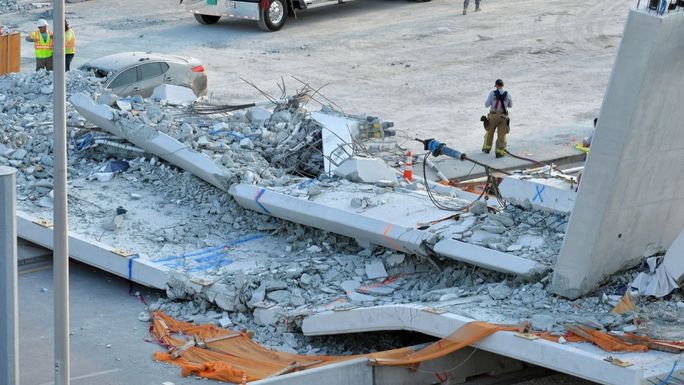
A US National Transportation Safety Board report into the collapse of a bridge during construction at Florida International University (FIU) in 2018 found that a range of failures contributed, one of which was the difference between the way a truss was supported during construction and the permanent support, which introduced stresses and caused part of the structure to crack. “This shows the importance of understanding the load paths during construction,” says Atkins’ Chris Mundell. “It is an exemplar of not thinking properly about how it was going to be built and the detailing.”

Florida International University bridge collapse, 2018
SCOSS also produced a report into the FIU bridge collapse, ‘Lessons learned from the 2018 Florida bridge collapse during construction’, which includes the recommendation that “a collaborative working arrangement, where the designer has a presence on site to expedite design decisions, and to relay design intent to improve outcomes for all parties, is preferred”.
It adds that a representative from the designer’s organisation “must attend site… to ensure construction is in accordance with the design, to ensure clear communication of the design intent, to allow expeditious dialogue to facilitate change, and to act as an independent pair of eyes and ears to improve quality and spot the potential for error”.
Alterations and demolition
Temporary load paths also need to be considered during demolition and structural alterations. Even the simplest alteration – such as taking out a structural wall or column in an apartment and inserting a supporting beam – requires an understanding of the load path of the entire building.
For example, the same thing may already have been done in the flat above, so the columns at either end of the new beam are already carrying more load than anticipated in the original design; or the wall may have been providing lateral support.
The same is true of what might appear to be a simple basement retrofit. “Undermining the foundations could cause a section of wall to collapse because you’ve taken away part of the load path,” says Dr Steve Jones, senior lecturer in structural engineering at the University of Liverpool. “Or the load finds an alternative load path and goes somewhere else, which leads to a collapse.”
A CROSS report into the collapse of a basement retaining wall in 2014, ‘Retaining wall excavation collapse’, highlights the need to ensure that the work carried out onsite is in accordance with what has been designed.
In this instance, a basement was being constructed under a terraced house and the engineer had designed it as a reinforced concrete box, isolated from the piles that supported the house. A methodology had been agreed – using ‘hit and miss’ underpinning, with 1.2m-wide pins – and the designer had provided a temporary works design for this construction methodology.
However, once construction started, the contractor altered the method, increasing the width of the pins from 1.2m to up to 3m, then the client asked for the basement length to be extended. For this extension, the contractor did not excavate in 1.2m-wide pins but instead excavated across the whole 6m width of the site. The designer had not provided a temporary works design for a 6m-wide excavation, and the excavation collapsed during construction.
Structural failures occur for one reason – the load path is not sufficient to carry the load on it. Whether the structure is simple or complex, in its permanent or temporary condition, it must always be possible to trace the path through the structure and identify where the load goes and how it is safely transferred from top to bottom.
Seven things I should ask before my design gets to site
- Do I know how it will be/can be assembled?
- How will it behave during construction?
- What impact does the construction sequence have on my design?
- Have I assumed a construction method in my design?
- Is there anything in my design that is very sensitive to construction tolerances?
- Have my important assumptions been communicated?
- What might go wrong and how could I de-risk it?
Sign up to receive news from ICE Knowledge direct to your inbox.